
In this tutorial, you will find a step by step guide on how to create a bevel gear in SolidWorks by using 3D features. I recommend that you play around and try to create different cogs and gears. Since almost all mechanical designs use gears and cogs they are very useful to know. A bevel gear might not be the most normal cog but it’s still a very important part.

Time required: 60 minutes
Difficulty: Beginner
Software: SolidWorks
There’s no specific exercise for this tutorial, the tutorial is an exercise in itself.
Looking for more exercises? Click here!
1. Open SolidWorks.
2. Open new part file.
- Click new

- Double click part
 in the new tab to create a new part document.
3. Select right plane, and click sketch ![]()
- To have a normal view on the selected plane, choose normal to
 from the click options.
 - You can also press space on your keyboard, to see the orientation panel. Then choose normal to.
4. On the sketch tab, click on line tool.
5. Using the line tool, click on the origin ![]() and draw the following geometry lines by using the SolidWorks horizontal, vertical, parallel and normal guidelines.
and draw the following geometry lines by using the SolidWorks horizontal, vertical, parallel and normal guidelines.
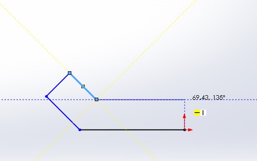
6. Click smart dimensions 
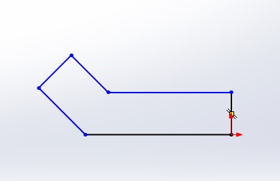
7. Dimension the geometry according to the example. Make sure it is fully defined.

8. Save and exit the sketch mode.
9. Select features toolbar.
10. Select sketch1 ![]() from the part tree.
from the part tree.
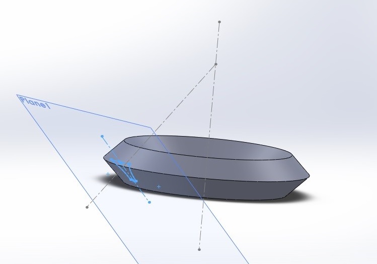
11. Click revolved boss/base  The revolve window will appear.
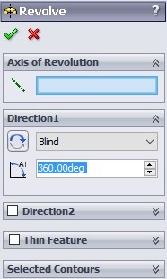
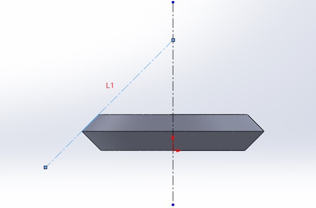
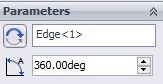
12. Click on the axis of revolution tab, then select L1 as the rotation axis.
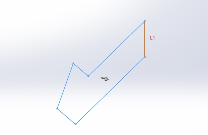
13. Make sure that your angle is set to 360 degrees, and click ok.

14. Select front plane and click sketch.
15. On the sketch tab, click on the line tool.
16. Choose the centerline option.
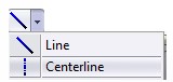
17. Using the centerline tool, draw a line which passes through origin.
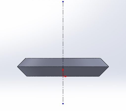
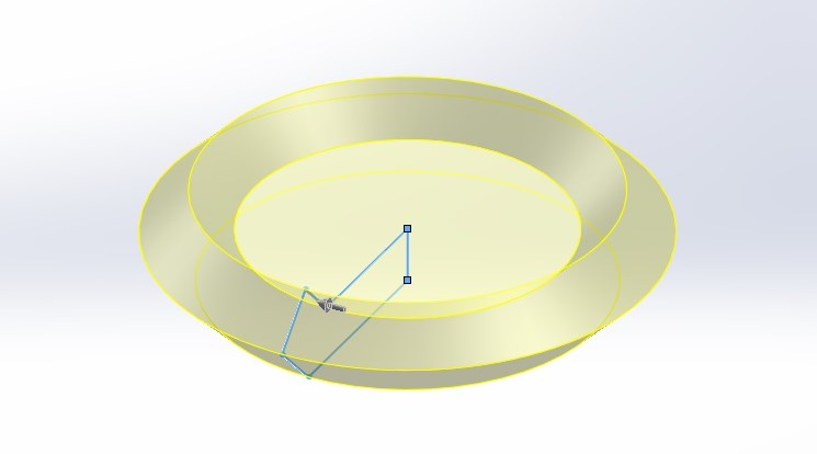
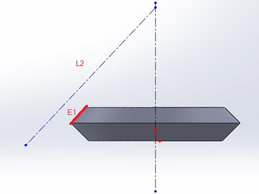
18. Draw another line according to the example.
19. Select L2 line and the E1 by holding the ctrl key at the time. The property manager window will now appear.
- The property manager window enables you to set different constraints and relation between entities.
20. In the properties window, select the collinear ![]() as a relation between these.
as a relation between these.
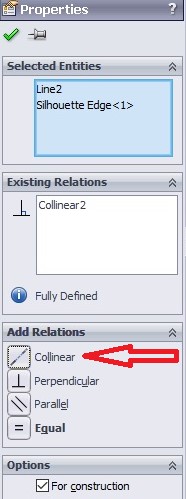
21. Press ok.
22. Save and exit the Sketch mode.
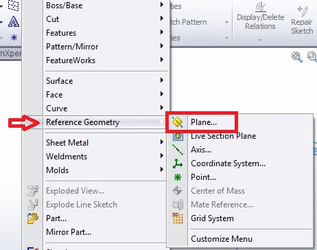
23. Click insert ![]() on main toolbar
on main toolbar
24. Go through insert -> reference geometry and select plane ![]()
25. In the property manager, click first reference then select face1 as a tangent face from the screen.

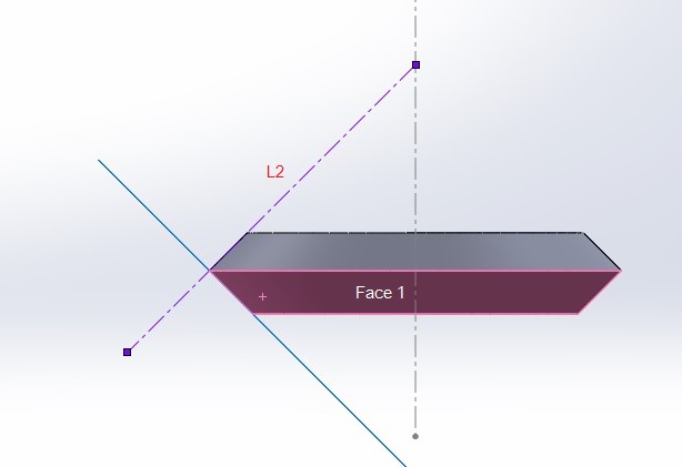
26. In the property manager, click second reference ![]() and select L2 as a perpendicular line from the screen.
and select L2 as a perpendicular line from the screen.
27. Select plane1 (the plane was created in the previous steps), and click sketch.
28. Press ok to insert the geometry plane.
29. On the sketch tab, click on line tool. Choose centerline ![]() option.
option.
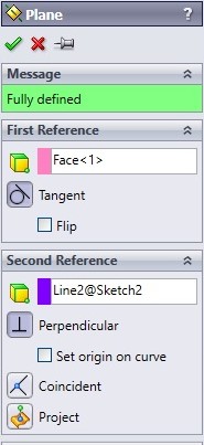
30. Using the centerline tool, draw a line which almost overlay the previous centerline.
31. On the sketch tab, click on line tool.
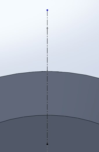
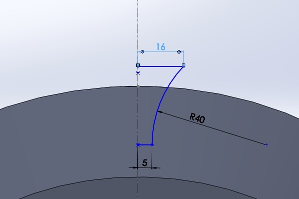
32. Using the line tool, draw the following geometry.
- The line tool can be used to draw different curves. For this purpose click on the screen for the starting point and then move back to the starting point and start to draw a curve.

33. Click smart dimensions.
34. Dimension the geometry according to the example.
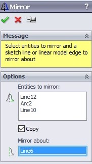
35. Click on mirror entities ![]()
- Mirror entities mirrors pre-existing 2D sketch entities on a plane around the selected line/centerline entity.
36. In the property manager, select the centerline as the mirror about. Select the drawn lines and curves as the entities to mirror.
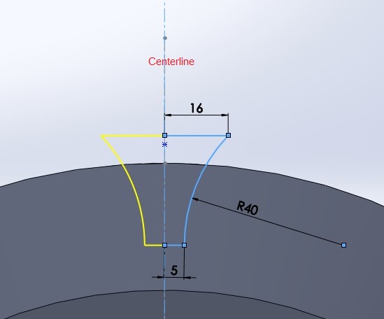
37. Press enter to place the mirror shape.
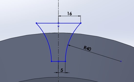
38. Save and exit sketch mode.
39. Select the features toolbar.
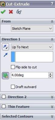
40. Click extruded-cut  The extrude-cut window will now appear.
- Extruded-Cut is a 3D feature which helps you to remove materials from the 3D model. You can cut in both directions and you are able to cut in angled extrusion by checking the draft option
41. Use the previous sketch as selected contours ![]()
42. Select up to next as the depth of cut ![]()
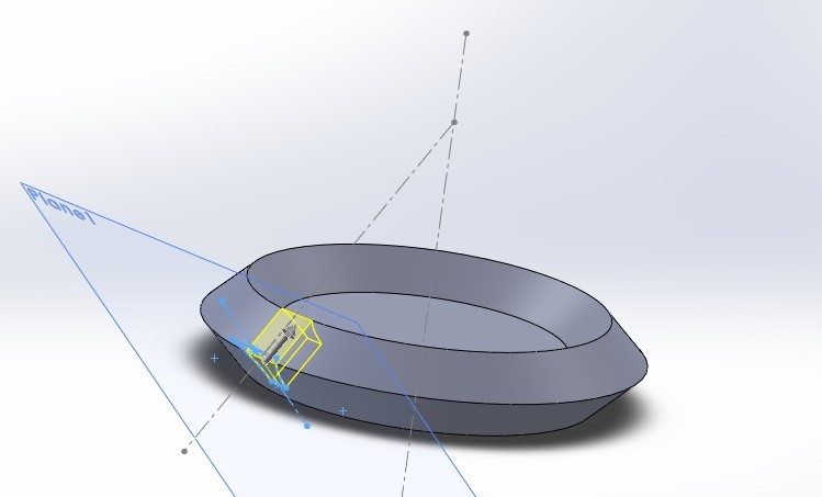
43. Check the draft ![]() feature, and set the angle to 4 degrees.
feature, and set the angle to 4 degrees.
44. Press enter.

45. On the features tab, click on the linear pattern toolbar list![]() and select circular pattern
and select circular pattern ![]()

- 3D pattern is a SolidWorks feature which helps you to remake features on a predefined pattern, such as lines, circles, curves, etc.
- 3D circular pattern is a 3D pattern feature which enables you to create the circular pattern using the feature you select as the seed feature.
46. In the property manager, select your extrude-cut as a features to pattern.

47. Set the angle parameter to 360 degrees.
48. Set the number of patterns to 25.
![]()
49. Check the equal spacing box.
![]()

50. Press enter.
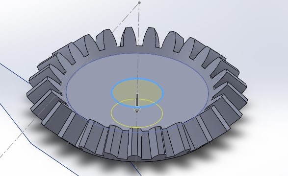
51. Click on the upper surface of the disk, and select sketch.
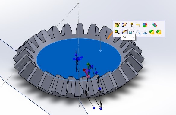
52. Using the circle tool, draw a circle centered at origin.
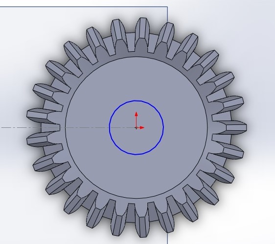
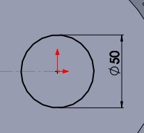
53. Dimension the circle by using the smart dimension, accordingly.
54. Save and exit sketch mode.
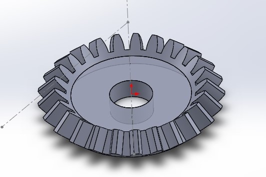
55. Click cut-extrude. The extrude-cut window will now appear.
56. Select the previous sketch as selected contours.
57. Select up to next as the depth of cut ![]()
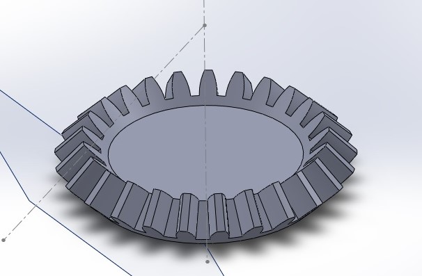
58. Press enter, you should now see a complete bevel gear in 3D!
59. Click file.
60. Click save.
Exercise 5 – Creating a bevel gear


excelente, estos ejercicios me ayudan a aprender el programa , thanyou
Victor – Excellent illustrated step-by-step instructions. Thank you!
Really appreciable!
Great effort and i found it really helpful.