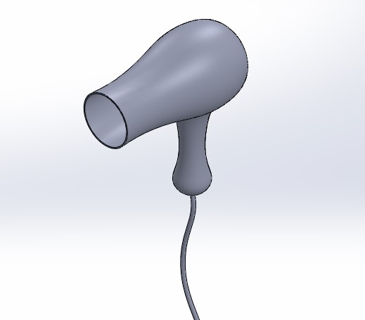
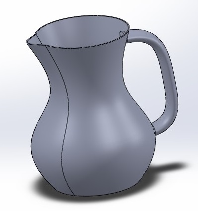
In this tutorial, you will learn how to use the loft feature by following a step by step guide on how to create this simple 3D geometry in SolidWorks, you will also learn how to use the sweep feature and a ton of other useful commands. As always there is a free CAD exercise at the end of this post, let me know if you need any help to figure it out!
Time required: 60 minutes
Difficulty: Beginner
Software: SolidWorks
Already know what to do and just want to do the loft feature exercise? Click here!
1. Open SolidWorks.
2. Create a new part file.
- Click new

- Double click part
 in the new tab to create a new part document.
3. Click insert ![]() on main toolbar.
on main toolbar.
4. Go via insert -> reference geometry and select plane ![]()

- SolidWorks reference geometries are a set of geometries which serve as an aid when you need to create sketches or features away from either the base datum planes or any existing part surfaces.
- There are several reference geometries: plane, axis, coordinate systems and point.
- Plane allows the user to create additional planes to sketch on other than the original planes or feature surfaces.
5. In the property manager, click first reference, then select front plane from the part design tree.

6. Select offset distance ![]() and enter 30mm as the distance between the parallel pages.
and enter 30mm as the distance between the parallel pages.
![]()
7. Check flip.
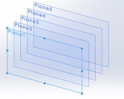
8. Enter 5 as the number ![]() of planes.
of planes.
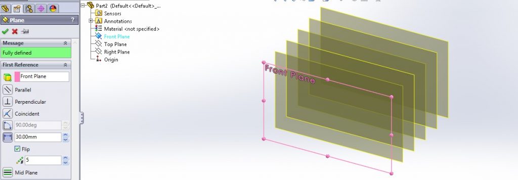
9. Press ok.
10. Select plane 1 and click sketch ![]()
- To have a normal view on the selected plane, choose normal to
 from the click options.
 - You can also press space on your keyboard, to see the orientation panel. Then choose normal to.
11. On the sketch tab, click on the circle ![]() tool.
tool.
12. Using the circle tool, click on the origin ![]() and draw a circle.
and draw a circle.

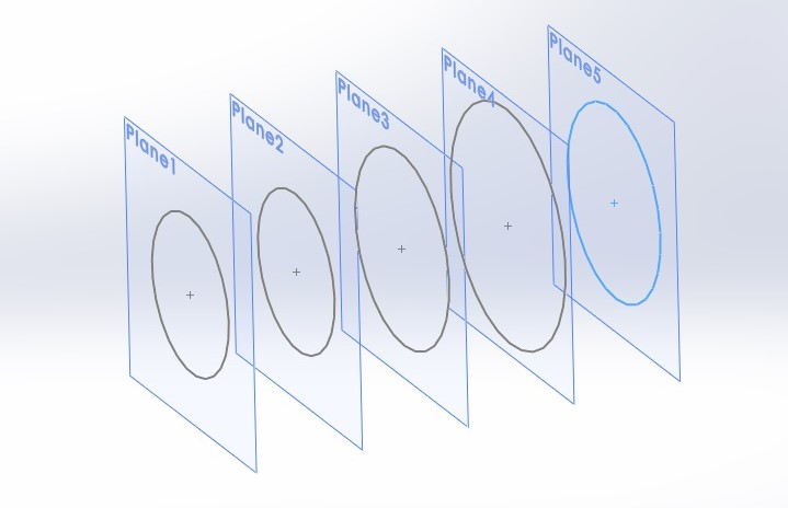
13. Exit the plane 1 sketch.
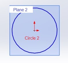
14. Select plane 2 and click sketch.
15. Repeat step 11 to 13 for this plane. Then draw a circle with the same size as circle 1.
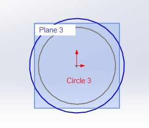
16. Select plane 3, and click sketch.
17. Repeat step 11 to 13 for this plane and draw a circle slightly larger than previous circles (pick a diameter that you feel comfortable with).
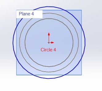
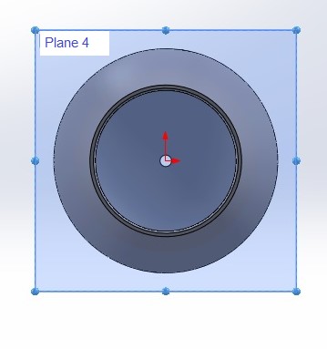
18. Select plane 4, and click sketch.
19. Repeat step 11 to 13 for this plane too, and then draw a circle slightly larger than circle 3.
20. Select plane 5, and click sketch.
21. Repeat the steps 11-13 for this plane, and draw a circle with the same size as circle 3.
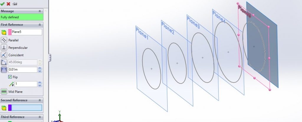
22. Select insert-> reference geometry-> plane.
23. Adjust the following settings (check the image below) in your property manager, and insert plane 6.
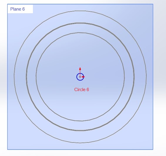
24. Select plane 6, and click sketch.
25. Repeat step 11 to 13 for this plane, and draw a small circle according to the example.
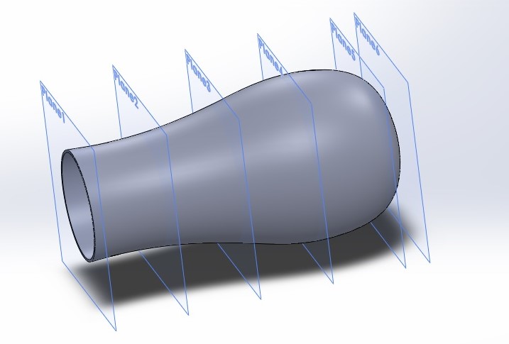
26. On the feature tab, select lofted boss/base ![]()
- The loft feature is a SolidWorks 3D feature which creates a shape by making transitions between multiple profiles and by using a guide curve (also called a guide rail).
27. In the property manager, click profiles ![]() . Select sketch 1 to 6 as the loft feature profiles from the design tree.
. Select sketch 1 to 6 as the loft feature profiles from the design tree.

28. Click thin feature to create a thin wall shape, then enter 10mm as the wall thickness ![]()
29. Press ok.
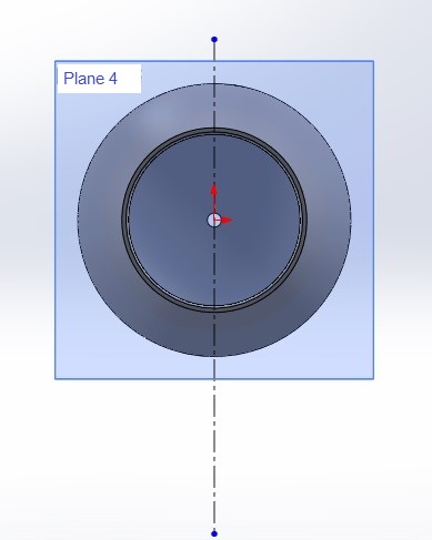
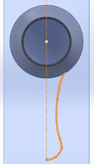
30. Select plane 4, and click sketch.
31. On the sketch tab, click on the centerline ![]() tool.
tool.
32. Using the centerline tool, draw a vertical line which passes through the origin.
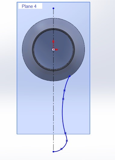
33. Click on the spline ![]() tool.
tool.
34. Using the spline tool, click on origin and start to draw a spline from the surface to the centerline according to the example.
35. Select the spline, and click offset entities ![]() on the sketch tab.
on the sketch tab.
- Offset entities is a sketching tool which enables you to offset entities edges or surfaces within a desired distance.

36. Enter 10mm in the dimension ![]() tab.
tab.
37. Press ok.
38. Close the drawn entities lower end by using the line tool, according to the example.
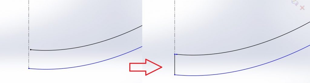
39. Close the drawn entities upper end by using the line tool.

40. Now that we have a fully closed sketch you should exit the sketch.
41. On the features tab, click revolved boss/base.
42. In the property manager tab, select the centerline as the axis.
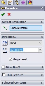
43. Click selected contours. Select the closed spline contour from the last sketch on the screen.
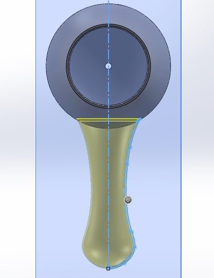
44. Press ok.
45. Select plane 4 and click sketch.

46. On the sketch tab, click spline ![]()
47. Using the spline tool, draw a spline starting from the handle midpoint.

48. Exit the sketch.
49. Select insert-> reference geometry-> plane.
50. Adjust the following settings in the property manager by choosing the top plane and handle midpoint.
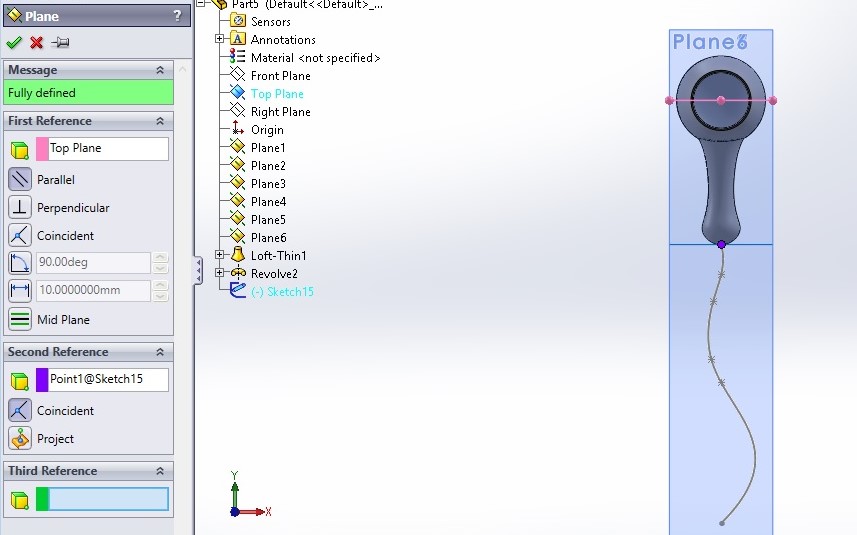
51. Insert plane number 7.
52. Select plane 7, and click sketch.
53. Click the circle tool.
54. Using the circle tool, draw a small circle at the handles midpoint.
55. Exit the sketch.
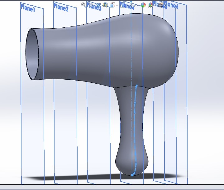
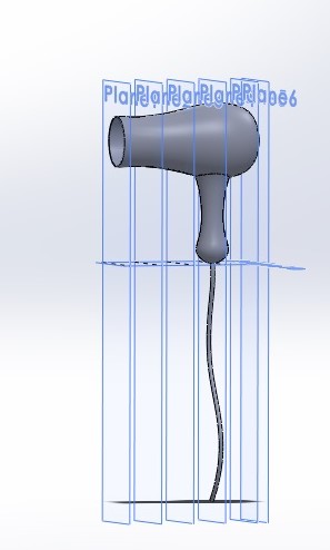
56. On the features tab, click swept boss/base.
- The sweep feature is a SolidWorks 3D feature which creates a shape by moving a 2D sketch profile along a 2D or 3D sketch path.
57. On the property manager select the circle sketch as profile ![]() , and the spline sketch as the path
, and the spline sketch as the path ![]()
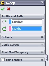

58. Click ok.
59. Click file.
60. Click save.
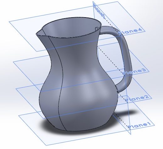
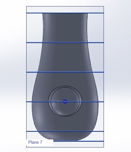
Exercise 4 – Using the loft feature to create a vase
- Practice the loft and sweep feature by modeling this example.
- You can use the following reference planes as help.