
Solidworks is a software package used for designing, manufacturing and analysis purposes by number of industries around the globe for their design requirements. Here we will understand about the user interface of Solidworks and main toolbars.
Below images shows the main elements of the Solidworks user interface:
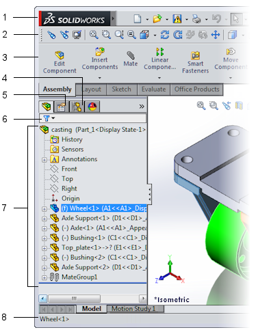
| 1 | Menu Bar |
| 2 | Toolbars |
| 3 | Command Manager |
| 4 | Configuration Manager |
| 5 | Property Manager |
| 6 | Feature Manager Filter |
| 7 | Feature Manager Design Tree |
| 8 | Status Bar |

| 1 | Heads-up View Toolbar |
| 2 | SolidWorks Search |
| 3 | Help Flyout Menu |
| 4 | Task Pane |
| 5 | Graphics Area |
Accessibility
Solidworks is easily accessible thanks to its readable font and very effective color schemes. In the property manger it uses colors to indicate the selection required for specific operations like faces, edges etc.
Windows and Displays
Solidworks displays every document in a separate window but we can arrange the windows to suit our needs. Solidworks has the capability to span two displays on screen.
Each part, assembly and drawing is a document in Solidworks and is displayed in a separate window. We can create a new window with another view of the document for viewing the current part, assembly or drawing. The cascade option arranges all the open documents so that the tile bars are visible for each document. Documents can be arranged horizontally or vertically to view all the open documents at once. In full screen mode the menu, status bar and feature manager designtree hides and graphic area shows on full screen.

Graphics Area
Reference triad shown in part and assembly documents helps to orient model and assemblies. Reference triad can also be used change the view orientation

To manipulate different objects like 3D sketch entities, parts, features and components in assemblies’ triad is used. Display of rings and wings of the triad depends upon the rotation and dragging possibility.

The models origin appears in blue and indicate 0, 0, 0 coordinates of the model, while origin appears in red in sketch mode.
All the common tools required to manipulate the views can be shown on Heads-up View Toolbar in each viewport.
![]()
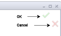
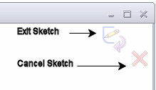
To accept features we create, there are many ways in Solidworks which includes right-click actions, confirmation corner, and standard property manager commands.
![]()
By right clicking in the graphics area multiple selection can be made and there are other filters are also available for different selections.
Set of pop up messages appear in the graphics area when we use some tools which are known as quick tips in Solidworks.
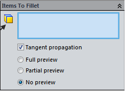
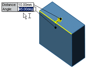
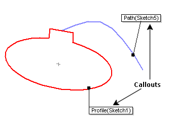
When we use specific tools text filled boxes appear in graphics area known as callouts. For dynamically clicking, moving and entering certain parameters without leaving the graphics area handles can be used.

Shaded preview appears when we apply some feature on a sketch and helps to visualize the operation we are doing. Rotate, pan and zoom functions can be used while in shaded view.
 While creating or editing a feature that supports dynamic previews, dynamic preview can be seen on the graphics window when pointer is moved.
System color options can be changed by clicking options in standard toolbar, or by going to tools -> options and then select colors.
The model can be viewed by one, two or four viewports
![]()
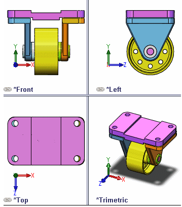
Image capture captures the graphics area of the window on clipboard
![]()
Video of the actions performed in the graphics area can be captured with Recording Video 
Manager Pane
Part and assembly designs, drawing sheets, properties, configurations, and third party applications are managed by Solidworks window manager placed on the left panel.
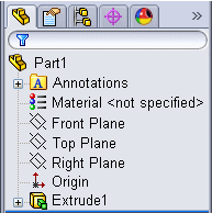
Features created are displayed from top to bottom on the FeatureManager Design tree in the order created.
Property manager displays in the left pane when we select a sketch, feature and drawing tool. It displays the properties of the feature without need of separate dialog box to prevent covering the graphics area.

For creating, selecting and viewing multiple configurations of parts and assemblies configuration manager is used.

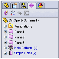
DimXpert manager shows the tolerances defined by dimXpert for parts; it displays dimXpert tools used to insert dimensions and tolerances into parts as well.
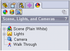
Appearances, decals, scene, lights, and camera that are applied to active model can be accessed by using display manager.
Commands, Menus, and Toolbars
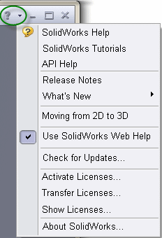
Menus contain all the SolidWorks commands, pause the pointer on SolidWorks logo in the upper left hand corner and click![]()
to display the menus. Frequently used tools from the standard toolbar, SolidWorks menus, SolidWorks search and a flyout menu of Help options can be found on Menu Bar.
![]()
![]()
![]()
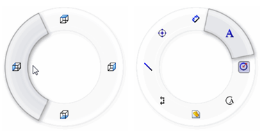
Mouse gestures can be used by right-dragging the mouse in the graphics area in part, assembly or drawing environments. Mouse gestures can be enabled or disabled, and number of gestures can be customized. There are four gestures defined by default.
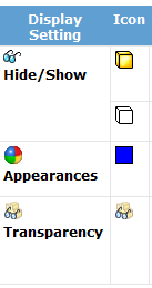
In part and drawing documents various display settings are available in the Display pane.

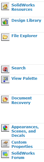
SolidWorks resources, libraries of standard parts, view to drag on sheets, and other useful items and information can be accessed through Task Pane.
Information related to the operation you are performing can be seen on the Status bar, to show or hide the Status bar click on View>Status Bar. It is placed at the bottom of the SolidWorks window.
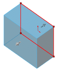
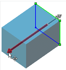
![]() Instant3D can be used to create and modify model very quickly by dragging handles and rulers. To enable Instant3d click on Instant3D toolbar on Features toolbar
Instant3D can be used to create and modify model very quickly by dragging handles and rulers. To enable Instant3d click on Instant3D toolbar on Features toolbar
![]()


