
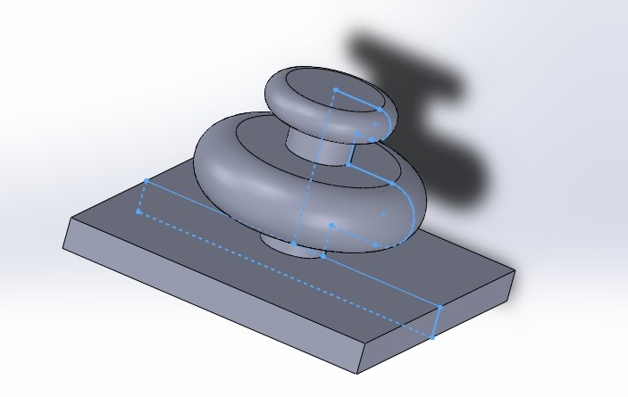
In this tutorial, you will find a step by step tutorial on how to create a 3D model in SolidWorks by using 2D sketching tools and 3D features. It will also have one exercise and examples on how to do the different tasks. The geometry that you will create should look like this.


Time required: 60 minutes
Difficulty: Beginner
Software: SolidWorks
Already know what to do and just want to do the exercise? Click here!
1. Open SolidWorks.
2. Click files in the main toolbar.
3. Click new ![]()
4. Double-click part  in the new tab to create a new part document.
5. Choose top plane from the design tree, and click sketch ![]()
- To have a normal view on the selected plane, choose normal to
 from the click options.
 - You can also press space on your keyboard to see the orientation panel. Then choose normal to.
6. On the sketch tab, click on line ![]() tool.
tool.
7. Using the line tool, click on origin ![]() and start to draw the geometry lines by using SolidWorks’ horizontal and vertical guidelines.
and start to draw the geometry lines by using SolidWorks’ horizontal and vertical guidelines.

8. Click smart dimensions 
9. Dimension the geometry according to the example.
 10. Click arc
 ![]() on the sketch tab.
on the sketch tab.
11. Select tangent arc.
 12. Click on the P1 point.
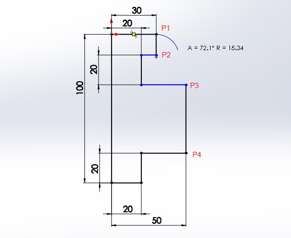 13. Drag the mouse to draw the arc.
14. Click on P2 point to place the arc.
 15. Click trim entities
 ![]() on the sketch tab.
on the sketch tab.
16. Select trim to the closest  from the property manager.
17. Using this trim tool, select the L1 side to make it bold.
 18. Click on it to trim it away.
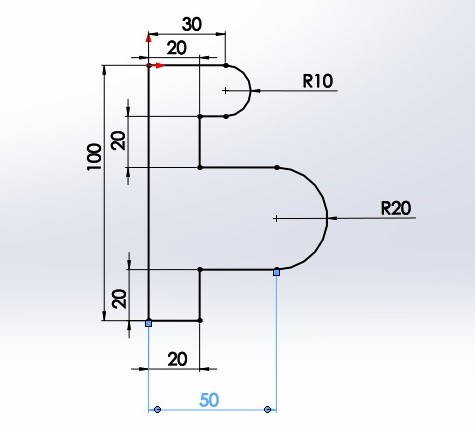
 19. Repeat steps 10 to 18 and draw a tangent arc between P3 and P4, then trim the line between them.
 20. Click smart dimensions
21. Dimension the arcs according to the example.
 22. Click line.
23. Draw the rectangle shape by using the line tool.
 24. Dimension the whole geometry according to the example. Make sure that it is fully defined.
25. Save and then exit sketch mode.
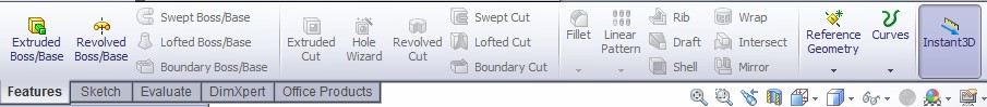
26. Select the features toolbar.
- The features toolbar is a collection of all the basic 3D design tools.
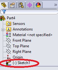
27. Select Sketch1 on your property tree.
 28. Click extruded boss/base
  in the features toolbar. As you click on extrude tool the direction- and property manager will appear.
- Extrude is one of the most frequently used tools in SolidWorks. It enables you to convert a 2D sketch into a 3D model.
- It comes with an advanced property manager which has directions, materials, thin features and draft sections.

29. Hover your mouse around the sketch and make the rectangle contour bold, then click on it.
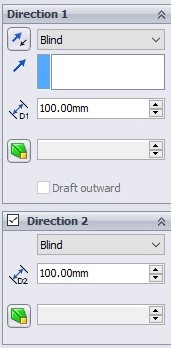
 30. Adjust the length of the extrude in direction 1 and direction 2 by entering 100 in dimension fields of the property manager (
 ![]() and
and ![]() ).
).
 31. Click OK
 ![]() to extrude the sketch.
to extrude the sketch.
 32. Select sketch1 again.
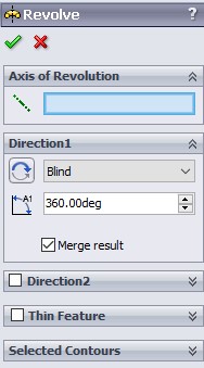
33. Click revolved boss/base 
- Revolve feature builds your 2D sketch into a 3D model by rotating your sketch about the defined axis.
- This feature has an axis, directions and a thin feature.
34. Hover the mouse around the sketch contour to select it.
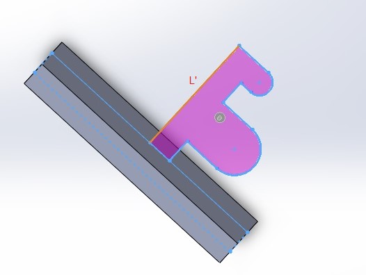
 35. Click on the axis tab, and then select the L as the rotation axis.
 36. Make sure that your angle is set to 360 degrees, and then click.
 37. Click fillet
 ![]()
38. Using the fillet tool, select the following edges.
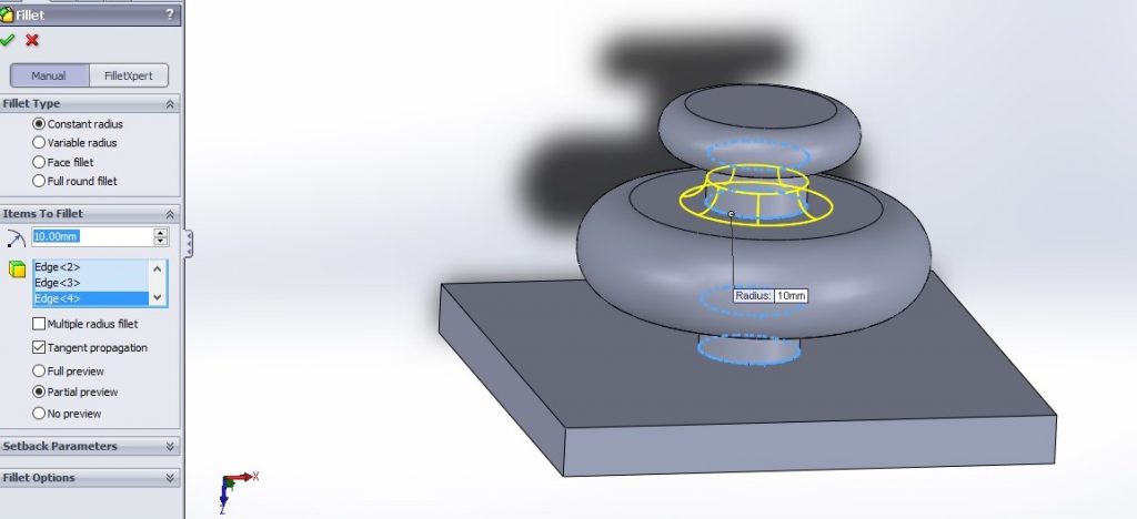 39. Set the fillet radius to 5 mm, and press enter.

40. Click file.
41. Click save.
Exercise 3 – Creating your first 3D model
- Practice what you have learned by modeling this example.

- You can start by drawing the following sketch.


